Knowledge Hub Search – Search All Our Sites

Operating Department Smart Search


Sort :
Loading...
Go to Page :
Showing posts with label WDG - 3A Locomotive. Show all posts

Mar 12, 2023

सहायक लोको पायलट के कर्तव्य (Duties of Assistant Loco Pilot)

सहायक लोको पायलट के कर्तव्य सहायक लोको पायलट के सामान्य कर्तव्य.
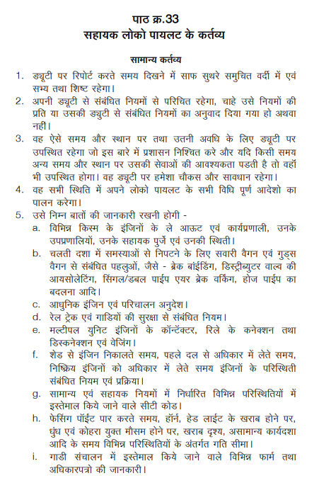
  1. ड्यूटी पर रिपोर्ट करते समय, दिखने में साफ सुथरे समुचित वर्दी में एवं सभ्य तथा शिष्ट रहेगा।
  2. अपनी ड्यूटी से संबंधित नियमों से परिचित रहेगा, चाहे उसे नियमों की प्रति या उसकी ड्युटी से संबंधित नियमों का अनुवाद दिया गया हो अथवा नहीं।
  3. वह ऐसे समय और स्थान पर तथा उतनी अवधि के लिए ड्यूटी पर उपस्थित रहेगा जो इस बारे में प्रशासन निश्चित करे और यदि किसी समय अन्य समय और स्थान पर उसकी सेवाओं की आवश्यकता पड़ती है तो वहाँ भी उपस्थित होगा। वह ड्यूटी पर हमेशा चौकस और सावधान रहेगा।
  4. वह सभी स्थिति में अपने लोको पायलट के सभी विधिपूर्ण आदेशों का पालन करेगा।
  5. सहायक लोको पायलट निम्न बातों की जानकारी रखनी होगी
  6. विभिन्न किस्म के इंजिनों के ले आऊट एवं कार्यप्रणाली, उनके उपप्रणालियों, उनके सहायक पुर्जे एवं उनकी स्थिती की जानकारी रखनी होगी ।
  7. b. चलती दशा में समस्याओं से निपटने के लिए सवारी वैगन एवं गुड्स वैगन से संबंधित पहलुओं, जैसे - ब्रेक बांईडिंग, डिस्ट्रीब्युटर वाल्व की आयसोलेटिंग, सिंगल/ डबल पाईप एयर ब्रेक वर्किंग, होज पाईप का बदलना आदि की जानकारी रखनी होगी ।
 
  1. आधुनिक इंजिन एवं परिचालन अनुदेश की जानकारी रखनी होगी ।
 
  1. रेल ट्रेक एवं गाडियों की सुरक्षा से संबंधित नियम की जानकारी रखनी होगी ।
 
  1. मल्टीपल युनिट इंजिनों के कॉन्टेंक्टर, रिले के कनेक्शन तथा डिस्कनेक्शन एवं वेजिंग की जानकारी रखनी होगी ।
   
  1. शेड से इंजिन निकालते समय, पहले दल से अधिकार में लेते समय, निष्क्रिय इंजिनों को अधिकार में लेते समय इंजिनों के परिस्थिती संबंधित नियम एवं प्रक्रिया की जानकारी रखनी होगी.
 
  1. सामान्य एवं सहायक नियमों में निर्धारित विभिन्न परिस्थितियों में इस्तेमाल किये जाने वाले सीटी कोड की जानकारी रखनी होगी ।
  2. h. फेसिंग पॉईंट पार करते समय, हॉर्न, हेड लाईट के खराब होने पर, धुंध एवं कोहरा युक्त मौसम होने पर, खराब दृश्य, असामान्य कार्यदशा आदि के समय विभिन्न परिस्थितियों के अंतर्गत गति सीमा की जानकारी रखनी होगी ।
  3. गाडी संचालन में इस्तेमाल किये जाने वाले विभिन्न फार्म तथा अधिकार पत्रों की जानकारी रखनी होगी ।
  4. यदि उसे दल नियंत्रक द्वारा या लॉबी इंचार्ज द्वारा गाडी संचालन के लिए कोई उपकरण दिया जाता है, उसे चार्ज में लेगा तथा उसका चार्ज सौपेंगा।
साईन ऑन के समय कर्तव्य
  1. सांस विश्लेषण के पश्चात ही वह साईन ऑन करेगा।
  2. वह सुनिश्चित करेगा कि उसके पास दो जोडी ऐनक है यदि डबूटी पर ऐनक की जरूरत पडती है तो ।
  3. सामान्य अनुदेशों एवं अन्य स्थानीय अनुदेशों आदि जैसे सभी अनुदेशों को वह पढ़ेगा। ड्यूटी के दौरान उसके सेक्शन पर पडने वाले संबंधित गति प्रतिबंधोको नोट करेगा।
  4. वह जांच करेगा कि रनिंग स्टाफ को उपलब्ध कराये गये सुरक्षा उपकरण जैसे सिग्नल, लैंप टॉर्च, फ्लैग, डेटोनेटर, फ़्यूजी चालू हालत में है।
चार्ज लेते समय कर्तव्य
  1. वह अंडरट्रक उपकरणों की जांच करेगा।
  2. वह फ्यूल ऑयल, ल्यूब ऑयल, वाटर लेवल, वाटर टेम्परेचर, गवर्नर ऑयल इत्यादी के लेवल की जांच करेगा। एक्सपांशन टैंक के सतह की जांच करते समय यह सुनिश्चित करेगा कि इंजन नॉन इलेक्ट्रीफाईड ट्रेक पर खडा है।
  3. वह हैंड ब्रेक की कार्य प्रक्रिया की जांच करेगा तथा सुनिश्चित करेगा कि जब गाडी रवाना होना हो तो हैंड ब्रेक ऑन नहीं है।
  4. वह सैंड बॉक्स में सैंड की जाँच करेगा, सैंड पर्याप्त मात्रा में तथा नमी रहित होना चाहिए।
  5. निम्न परिस्थितियों में सहायक लोको पायलट, लोको को लोड के साथ कपल एवं अनकपल करेगा -
  6. a) प्रारंभिक स्टेशन पर
  7. b) इंटरमिडिएट पॉईंट पर
  8. c) इंजिन चेंजिंग के समय
  9. d) स्टेशन या यार्ड में जहाँ लोकोमोटिव डिटैच करना हो। यार्ड से गाडी निकालते समय यह कार्य शंटिंग स्टाफ के मदद द्वारा किया जायेगा।
  10. वह संरक्षा मदों तथा साधनों जैसे हैड लाईट, सुचारू संचलन के लिए फैलशर लाईट, सही दृश्यता के लिए शीशे के देखरेख, बी.पी प्रेशर एवं सही वैक्युम मात्रा की जांच करेगा।
  11. लिकेज एवं ट्रबल शुटिंग आदि के लिए इंजन की जांच करने में लोको पायलट की सहायता कर
  12. वह सुनिश्चित करेगा कि निम्नलिखित इंजिन पर उपलब्ध है
a) स्पेयर VRR फ्युज b) मल्टीपल युनिट केबल c) स्पेयर कपलिंग d) स्पेयर होज पाईप e) बुडन वेज f) कपलिंग कलैम्प g) फायर एक्स्टींगुशर
  1. यह सही MR प्रेशर तथा BP प्रेशर उपलब्ध है, यह सुनिशिचित करेगा।
  2. जब कभी दल नियंत्रक या लॉबी इंचार्ज द्वारा पोर्टेबल फिल्ड टेलिफोन PFT सुपुर्द किया जायेगा उस समय सहायक लोको पायलट उसे एकत्रित करेगा और सुनिश्चित करेगा कि चलती गाडी में सेफ कस्टडी में है तथा साईन-ऑफ करते समय लॉबी को वापस करेगा।
गाडी चलते समय कर्तव्य
  1. वह सिगनल को देखने में लोको पायलट की सहायता करेगा। वह दृश्यता दूरी से सिगनल, कॉशन बोर्ड, स्पीड इंडिकेटर्स द्वारा प्रदर्शित पहलुओं को बतायेगा।
सिगनल सत्तर्क चलान क्षेत्र पर पहुचते समय वह अन्य किसी कार्य में अपने आपको व्यस्त नहीं करेगा।
  1. वह यात्रा के दौरान पीछे मुडकर देखता रहेगा कि गाडी सुरक्षित और सही तरीके से अनुगमन कर रही है। विशेष रूप से मोड पर जहाँ पूरी गाडी दिख सके और यह सुनिश्चित करेगा कि गाडी पूर्ण रूप में है। जब गाडी लाईन पर चल रहे कार्य-स्थल या मानव चलित फाटक से गुजर रही हो तो सहायक लोको पायलट यह सुनिश्चित करने के लिए पीछे देखेगा कि सब कुछ ठीक है और यदि कोई सिगनल दिया जा रहा हो तो, सुनिश्चित करेगा की वह किसी दुर्घटना की जानकारी तो नहीं दे रहा है।
  2. वह दूसरी लाईन से गुजर रही गाडीयों की निगरानी रखेगा और यदि कोई असामान्यता दिखायी देती है तो लोको पायलट को सूचित करगा। यदि आवश्यक हो तो दूसरी गाडी के गाडी को खतरा सिगनल दिखायेगा।
  3. जब लोको पायलट द्वारा प्रतिनियुक्त किया जाता है तो वह लोको पायलट की ओर से सिगनल का आदान प्रदान करेगा।
  4. लाईन पर किसी प्रकार कि अनियमितता जैसे - ए.सी.पी., होज पाईप डिसकनेक्शन, ब्रेक बाईंडिंग, हॉट एक्सल को देखने का उत्तरदायित्व उसका होगा।
  5. सभी प्रकार के असामान्य संचालन, टी.एस.एल, सभी संचार व्यवस्था में खराबी, सिगनल में खराबी, लोड पार्टिंग, लोड डिव्हाईडिंग, दुर्घटना इत्यादी के दौरान उसे अत्याधिक सतर्क एवं सजग रहना होगा।
  6. वह MR, MR2. J Filter, ड्रेन कॉक को खोलकर नमी निकालेगा, बचे इंधन की जांच करेगा, अंडरफ्रेम उपकरणों की जांच करेगा और जब गाडी 15 मिनिट से अधिक समय के लिए रूकती है तो एक्सल बॉक्स की गरमाहट की जांच करेगा (मेल एक्सप्रेस, पैसिंजर ट्रेन पर कार्य करने के मामलों में समय सीमा पूर्व निर्धारित हॉल्ट के कारण लागू नहीं होगी)
  7. वह प्रति 30 मिनिट पर विभिन्न ऑईल एवं एयर प्रेशर, स्पीड, नॉंच आदि को रिपेयर बुक में नोट करेगा। वह गाडी संचालन के समय को भी रिकॉर्ड करेगा।
  8. कार्य करने योग्य वातावरण बनाये रखने के लिए वह ड्रायव्हर कैब को साफ सुथरा रखेगा।
  9. जब इंजन को लोको के काम के लिए हटाया जायेगा तब वह इंजिन को अलग करेगा।
  10. यदि लोकों पायलट गाडी चलाने में असमर्थ हो तो, धीरे-धीरे A- 9 द्वारा ट्रेन ब्रेक लगाकर गाडी को खडा करेगा और नियमानुसार गाडी का बचाव करेगा उसके बाद वह गार्ड को सूचित करेगा और जितनी जल्दी हो सके SM & Controller को इसकी सूचना भेजेगा। यदि वह योग्यता प्राप्त और उसके पास लोको पायलट योग्यता प्रमाण पत्र हो तो वह गार्ड को सूचना देने के बाद कि वह सहजता पूर्वक काम करे, ब्लॉक सेक्शन क्लिअर करेगा।
  11. सिंगल लाईन सेक्शन पर जहाँ बॉल टोकन चलती गाडी में दिये-लिये जाते है उसे यह सुनिश्चित करना चाहिए कि पिछला बॉल टोकन प्राधिकृत स्टेशन कर्मचारी को सौंप दिया गया है और उपयुक्त नया बॉल टोकन ले लिया गया है।
  12. यदि इंजिन ब्लॉक सेक्शन में बंद पड जाता है या खराब हो जाता है तो लोको पायलट से परामर्श करके वह हैंड ब्रेक और वुडन वेजेस लगायेगा और गाडी का संचालन रोकने के लिए वैगन को पिन डाऊन करेगा।
  13. यदि गाडी के पटरी से उत्तरने पर उसकी गाडी उसमें उलझ गई हो तो वह लोको पायलट की सहायता इस प्रकार से करेगा -
  14. फ़्लैशर लाईट ON करेगा।
  15. यदि फ़्लैशर लाईट खराब हो तो हेड लाईट का स्विच ऑन, ऑफ करके
  16. c. डबल लाईन सेक्शन पर बगल की लाईन का और सिंगल लाईन सेक्शन पर यातायात की दिशा में अपनी लाईन का बचाव करके वह अन्य लाईन लाईन के लोको पायलट /अन्य रेल कर्मचारी की सहायता लेकर/ फिल्ड टेलिफोन द्वारा/ समीप के समपार फाटको पर/ नियंत्रक को सूचना देने तथा नजदीक के रेलवे स्टेशन पर मेमो देने में लोको पायलट की सहायता करेगा।
  17. यदि किसी कारण वश चलती गाडी में पिछला सिगनल पार करने के बाद खतरे की संभावना का पता चलता है या ट्रेन चलने में कोई बाधा है तो लोको पायलट को ट्रेन रोकने के लिए सूचित करने के बजाय वह आपातकालीन ब्रेक लगाएगा
उपरोक्त के अलावा जीआर एंड एसआर या स्थानीय अधिकारियों द्वारा जारी निर्देशों और मुख्यालय अधिकारियों द्वारा समय-समय पर जारी किए गए निर्देशों का भी पालन करेगा।  

Duties of Assistant Loco Pilot 

General duties 

1. While report on duty he must be in proper uniform and well disciplined.
2. He should be aware of rules related to his duty, whether he is in possession or not a copy of rules or translated copy of rules.
3. He should be present on the time, at the place for duty which is assigned by administration, more ever if required on other place and time for his services. He should always alert and cautious while on duty.
4. In all conditions he should obey all lawful orders of his loco pilot.
5. He should have the knowledge of the following -
a. Lay out of all types of loco, its system and their sub systems, its subsidiary equipments with locations.
b. While on run able to trouble shoot the troubles of coaching and goods wagon like brake-binding, isolation of distributor valve, single/double pipe air brake working, changing of hose pipes etc.
c. Modern loco and operating instructions.
d. Safety rules related with track and train.
e. Connections, disconnection of multiple units, wedging of relay and contactor.
f. Rules and procedure of locomotive condition while taking charge from shed, from incoming staff, taking charge of dead locomotive.
g. Use of whistle code during various conditions as prescribed in GR&SR.
h. Speed limits in various conditions i.e. passing facing point, horn failure, head light failure, foggy weather, poor visibility, abnormal condition etc.
i. Various forms and authorities used in train operation.
6. He should take charge or hand over charge of equipment if given by lobby in charge/ crew controller for train operation

While Sign ON

1. He should sign on after breath analyzer test.
2. He should have two pair of spectacle to use on duty if required.
3. He should read all general and local instructions.
4. While on duty, he should note all speed restrictions related with section in which he is to be worked.
5. He ensure that safety equipment like torch, flag, detonator and flair signal, supplied to running staff is in working condition.

While Taking Charge

1. Check the equipments of under truck.
2. Check the level of fuel oil, lube oil, water, governor oil and water temperature etc. Ensure loco should be is on non electrified track while checking water level.
3. Check the hand brake working and ensure it should be released on train starting.
4. Check the availability of sand in sand box; it should be sufficient and dry.
5. ALP will detach/attach the loco with load in following condition
a. On starting station.
b. On intermediate point.
c. While loco checking.
d. On station/yard where it is essential to detach loco. This work is done with the help of shunting staff while train leaving from yard.
6. Ensure the working of safety item and equipment like head light, flasher light, level of BP pressure/vacuum and take care of look out glass for better visibility.
7. He should assist to loco pilot in trouble shooting, leakage arresting and loco checking.
8. He should ensure following safety items are available on loco
a) Spare VRR fuse
b) Multiple unit cables
c) Spare coupling
d) Spare hose pipes
e) Wooden wedges
f) Coupling clamp rew control/ lobby in charge will hand over portable field telephone, ALP will collect it and keep in safe custody while on run and hand over it in lobby while signing off.

While on Run

1. He should help to loco pilot in signal sighting. He should call out signals, caution board, speed board from adequate distance. He should not keep himself busy in any work while approaching to cautious signal region.
2. During train running he should look at back on curve and ensure that train is running intact and safe, especially on curve where full train is visible. When train is passing from working spot on track/ manned gate he should look out back to ensure that the train is all right and if any signal is exhibited regarding information of accident.
3. Keep watches on train passing on opposite track if notice any abnormality should report to loco pilot, if necessary show the danger signal to stop the opposite train.
4. Whenever deputed by loco pilot, he should exchange the signal on be half of loco pilot.
5. He should be responsible for keeping watch on abnormalities such as ACP; hose pipe disconnection, brake binding, hot axle, on line.
6. He should be more alert and vigilant while all type of abnormal working such as TSL, all communication failure, defective signal, load parting, load dividing, accident etc.
7. On hault he will drain out the moisture from MR1, MR2, J-Filter and check the fuel oil level and safety fittings. He will also check the temperature of axle boxes if train is stopped more than 15 minute. (Time limit is not applicable incase of mail express and passenger.)
8. He should note down the reading of various oil/air pressure, speed Notch position, etc. in every 30 minute. He should also record train running time.
9. He will keep loco pilot cab neat &clean to maintain cab environment.
10. He will uncouple the loco when loco is required detach for maintenance work.
11. If the loco pilot is not able to drive the train, he should stop the train by applying A-9 gradually & protect the train as per G&SR, then inform to guard & try to inform SM/SCOR immediately. If he is competent and having loco pilot competency certificate then he should clear the section after informing guard, that he should be alert.
12. In single line section where ball token is exchanged he should ensure that ball token is handed over to authorized station employee of previous station and new functional ball token is collected properly.
13. If loco is shut down or failed in section, he will apply the hand brake, wooden wedges and pin down the wagons to prevent from rolling down, after consulting with loco pilot.
14. If train is derailed or capsized, he will assist the LP in following manner
a. Put on flasher light.
b. If flasher light is defective, put on /off repeatedly head light switch.
c. By protecting opposite line in double line section , from front direction in single line section and he should help to LP for informing to controller / nearest station master by field telephone/nearest gate/ loco pilot of opposite train/with the help of other railway employee.
15. He will apply emergency brake instead of informing loco pilot to stop the train if he noticed any abnormality in running train after passing last signal or there is obstruction in running train. Above duties are not sufficient, he will also follow the GR & SR or instructions issued by local officers and instructions issued by headquarter officers time to time with any mean.


Jan 5, 2021

Microprocessor Control Loco

Microprocessor Control Loco (MEP-660) Now days, MEP-660 microprocessor is provided in diesel locomotive and such type of loco are called microprocessor control loco. New 11 series locos WDM3D and retrofitted WDG3A, WDM3A are microprocessor control locos. Their General Data as under -


Advantages of Microprocessor Control Loco  1. All Breakers and switches are similar to WDG3A except additional circuit breaker MPCB and PLPB for easy handling to LP 2. Very low intervention by the LP during faults trouble shooting activities by LP is simplified. 3. No reset of GR1, GR2 and GFOLR because sensors are provided for the same. 4. Pre and post lubrication feature is available. 5. Possibility of load stalling is very less. 6. Cold engine feature is provided. 7. No need to maintain the timings specified in load meter since MEP660 automatically reduces the excitation. 8. No need to regulate the Dynamic brake at high speed since MEP660 automatically reduces the excitation. 9. No slackness of cards on run. 10. Automatic isolation of TM at the time of short/open circuit. 11. More than one TM can be isolated. 12. Automatic reduction of transition speed in case of TM isolation. 13. Detailed audio video fault indications. 14. In case of locked axle system indicate clearly which wheel is locked
 
Changes in Microprocessor Control over convention WDG3A loco  1. All Breakers and switches are similar to WDG3A except additional circuit breaker MPCB and PLPB are providing on front panel. While engine starting both breakers should be in ON position 2. The pre-lubrication pump is provided in compressor room; it is use for pre-lubrication of engine before starting. 3. Following equipments are removed in this loco -ECP, VRP, TRP, BSR, TDR, BKR, CVR, TR, VRCLS, OVDR, LAS, TET, GR1, GR2, GFOLR, WSR1, 2, 3, Techo generator, axle generator, Excitation panel. 4. Following new equipments are provided in this loco – MEP-660 microprocessor control unit, display unit, distribution box (RDB & ADB1, 2,3,4), sensors (14current, 5voltage, 3temp, 7speed, 7pressure), TE limit switch, multi reset VCD. 5. Following Relays are provided in this loco – Out of 23 relays 13 relays are eliminated &10 relays retained. DMR, SANDER, VCDR, CMR, SLBR, SR, AGPR, EXPR MVR, AFLR. (FSR in WDM3D only)


1. DMR-   Dead Man Relay. Same as conventional Loco 2. SR-      Signal Relay. Same as conventional Loco. 3. MVR- Moisture Vent Relay. Or Magnet Valve relay. Same as Conventional Loco. 4. AGPR- Aux. Gen. Protection Relay. This relay is always be ON when the engine is running. The relay is OFF during cranking. 5. EXPR- Exciter protection relay. This relay is always ON when the engine is running. The relay is OFF during cranking.. 6. CMR- Compressor Relay. This relay is ON when the MR pressure is more than 10 Kg./cm2 . The relay is OFF when the pressure is less than 8 Kg./cm2 . 7. VCDR- Vigilance control device relay. This relay is normally in ON position. During penalty bake application, this relay is OFF. 8. AFLR- Auto flasher Light relay. This relay is normally ON while running. During un-authorized BP reduction, this relay is OFF and flasher lights are switched ON. 9. SLBR- Self load box relay. This Relay This relay is ON when self load box test is selected from display unit. 10. SANDR-During wheel slip, after 15% power reduction, the sander relay is ON Wheel slip indication is ON to the driver. Automatic sanding is done. 11. FSR- Field shunting Relay. This relay is available in WDM3D Locos only. OFF.


Engine starting procedure: Before engine starting check the locomotive (safety fittings, oiling points, water level, etc.) and ensure wooden wedge & hand brake in applied condition. Then start the Diesel engine by following sequence - 1. Put ON Dome light breaker and Dome light switch. 2. Indication - Dome light will glow. 3. Close the BS in Nose room. 4. Ensure MUSD1&2 on RUN and ECS on Idle. 5. Put ON MB1& MB2 on front panel. 6. Put ON MFPB1&2 on control stand. 7. Put ON CEB, DEB, RBB on front panel. 8. Put ON FPB on front panel. 9. Put ON MCB1&2. 10. Press the alarm push button three times on front panel for ringing bell. Then put OFF MCB1&2. 11. Put ON MPCB and PLPB and wait till Idle Screen display on Display Unit
 
12. Press and hold the Start Button, pre-lubrication is starts. After 60 seconds cranking contactor will pick up and engine will crank. When lube oil pressure builds up to 1.3 kg/cm2, then release start button. 13. Put ON AGFB on front panel Engine stopping procedure 1. Secure the Loco. 2. Keep MH handle on Idle and reverser handle in neutral. 3. Keep ECS on Idle position. 4. Ensure that all CB are ON. 5. Press stop button, till main crank shaft will stop. 6. “Post lubrication in progress keeps all circuit breaker ON” message will display on display screen for 5 minutes. 7. After completion of post lubrication put all circuit breakers ‘OFF’ 8. Put BS in ‘OFF’ Display Unit  It is provided on front panel. When MB1, MB2, MPCB kept ON during engine starting it shows idle parameter of loco. Further it changes according to the loco pilot operation i.e. motoring display, braking display. It also shows fault messages when fault comes on loco.
 
 
Procedure of Fault Resetting Maximum faults are reset automatically after fault recovery, some faults are recovered after keeping throttle on idle and other require acknowledging but some required to reset manually. Procedure of Manual Reset of Faults  1. Following modes will display on display unit after pressing MENU button - 1. Faults 2. Display Mode 3. Test Mode 4. Exit 2. Then pressing no.1 key on key pad following be display - 1) View active faults 2) Clear active faults On pressing no. 2 key on key pad fault information will display, on pressing no.0 key on key pad followed by Enter button, fault will reset and next fault will display in this way clear all faults by pressing 0 and Enter key till message will appear No more fault, press menu button to exit. Transition Two transitions are provided in WDM3D loco, 1st transition takes place on 42 km/h from series parallel to series parallel field shunt and 2nd transition on 52 km/h from series parallel field shunt to parallel combination. In retrofitted loco only one transition takes place at 41.5kmph from series parallel to parallel combination. Motor Cut out Switch (MCOS) Six toggle switches are provided in front panel to isolate individual TM. For isolation of TM related toggle switch to be made off. With the help of these switches more then one TM can be isolated. Auto transitions also come even though TM isolated. Loco power and auto transition speed setting is reduced proportionate to no. of TM isolate and transition will take place on lower speed. Vigilance control device (VCD)  VCD alerter is provided on loco to alert loco pilot in every 60 sec, if loco pilot is not alert penalty brakes were applied through VCD. VCD alerter will work if BC pressure is less than 2.0kg/cm² and MB1, MB2, MPCB, MFPB1&2, MCB1&2 should be in ON position. VCD can be made inactive by loco pilot if one of the activities is carried out with in 60 sec - 1. Changing the position of throttle
 
2. Changing the position of A9 3. Application/releasing of dynamic brake 4. Change of DB level. 5. Operation of GFCO 6. Operation of sander switch 7. Pressing of horn switch 8. Changing the position of RH 9. Pressing of VCD reset button From the above if none of activity is carried out by loco pilot with in 60 sec, VCD lamp will glow and made loco pilot alert for 08 sec. If one of the activities from above is carried out by loco pilot, VCD will reset. If none of activity is carried out by loco pilot after VCD lamp glowing with in 8 sec then VCD buzzer will sound along with the lamp for next 8 sec and message will be display VCD time out press VCD reset on display unit. In this way 76 sec ( 60+8+8) is given to loco pilot to reset VCD, if he fails to reset, penalty brakes will applied with following changes on loco - 1. BP pressure will drop up to 2.8 kg/cm². 2. Buzzer stops sounding. 3. Engine speed comes to idle. 4. GFC contactor will drop and power contactor will also drop on bring throttle on idle and 5. Message will display VCD applied penalty brakes, press reset button to reset penalty brake. 6. VCD counter on display unit increase by one. Procedure of Resetting VCD (Penalty Brake)  1. Keep throttle handle on idle 2. Loco should be stand still 3. Wait till VCD lamp is extinguished. 4. Press VCD reset button Note 1. MCB1&2 to be kept off before starting the engine otherwise VCD will operate. 2. On hault BC pressure should be more than 2.0 kg/cm² to inactive the VCD in standing position of loco. 3. In trailing loco of multiple unit MCB1&2 should be kept in ON position otherwise VCD will operate but penalty brake will not come and throttle will not respond in trailing loco


Power Ground :-  TANGI detected power circuit is grounded. Massage on Display Unit “1007 - Power Circuit Ground. Restrictions: Motoring Prohibited. Dynamic Brake Prohibited. Engine IDLE” With continuous alarm bell till throttle is brought to IDLE. Power is cut off. Engine RPM is brought to IDLE. Power contactors and GF are dropped out. Action taken by loco pilot-  Bring the throttle to IDLE and wait for 15 Sec. The fault is cleared automatically. Perform the checks as per the conventional WDG3a loco. Power circuit ground fault recovered for 5 seconds. If the fault is remain existing. The fault is logged again. Auto reset is permitted up to 3 times within 1 hour. There after manual reset has to be done. If the fault is occurred more than 3 times contact shed for further advice. Do not forget to write in the repair book. Over Load Fault:- Tr. Alternator Field current is more than 280 Amps. Massage on Display Unit- 1027-Alternator Field over current FAULT. Restrictions: motoring prohibited dynamic brake prohibited” With Alarm bell switched on for 30 seconds. Action by Loco Pilot:- Bring throttle to IDLE. The fault is reset automatically. Reset message is displayed. Trouble shoots as per GFOLR trip in normal WDG3A locomotives. Alternator field over current is reset for 5 seconds. If the fault is existing, the fault is logged again. Auto reset is permitted up to 3 times within 1 hour. There after manual reset has to be done. If the fault is occurred more than 3 times contact shed for further advice. Do not forget to write in the repair book.
 
Hot Engine Alarm Fault:-  1. When water temperature raises up to 90o C. Message on Display Unit - 2008 Warning: ENGINE Temperature High. Reduce Power” for 5 seconds. Alarm bell is switched ON continuously till temperature is less than 85o C. Action by Loco Pilot:- If possible do fast pumping manually. Otherwise Power is de-rated by 20% per every degree of temperature raise from 90oC onwards. 910C-                      20% power de-rated 920C-                      40% power de-rated 930C-                     60% power de-rated 940C-                      80% power de-rated Driver can work with reduced power up to 950C. 2. When water temperature is more than 95o C Message on Display Unit -“1006 - HOT ENGINE. Can’t Power UP. Restrictions: Motoring Prohibited Dynamic Brake Prohibited” Along with buzzer continuously in addition to alarm bell. GF and power contactors are dropped out. Engine RPM is automatically raised to 8th notch irrespective of notch position. If reset button is pressed or after 30 seconds “2026 - HOT ENGINE. Can’t Power UP Restrictions: Engine is running at 8th notch. Motoring Prohibited. Dynamic Brake Prohibited. “Along with buzzer. Action Taken by Loco Pilot:- Apply train brakes. Wait till the water temperature is reduced below 90oC. Bring the master handle to IDLE. Engine speed reduces to IDLE automatically. Buzzer and message stops.
 
Auxiliary Power Unit 
 
Procedure of Loco Handling and Its Precaution 1. Loco starting and braking system is similar to WDG3A (conventional). 2. Whenever needle of load meter showing restricted zone, do not ease the throttle, microprocessor will reduce power automatically. 3. When ever loco direction is require to change, loco should be stand still. When loco is running and reverse handle is operated, reverser will not change its position. 4. Do not ease the throttle when wheel slip occurs, microprocessor will reduce power automatically. Trouble shooting is similar as WDG3A (conventional). If trouble is because of drizzling /oily track /wet track than reduce the notch as per requirement. 5. When water temp become 900C, hot engine indication will come, do not reduce the notch, microprocessor will reduce power automatically (20% power will reduce automatically on each degree of rising water temp above 900C) when water temp become 950C, GFC and power contactor will drop automatically and loco power becomes zero, due to this load can be stall, apply train brake to avoid roll down. In this situation engine will race on 8th notch automatically for cooling the water, keep TH on idle and acknowledge the fault on display unit, wait till the engine speed comes on idle. 6. Whenever power ground or field over load occur, keep throttle on idle fault will reset automatically , if fault occurs three time in a hour reset it similarly. If fault occurs fourth time inform PCOR and reset it manually, trouble shooting is the same as WDG3A. 7. When there is trouble while train starting, ensure position of TE limit switch it should be in normal position otherwise tractive effort will be limited. 8. The loco which is provided with ‘cold engine speed limit feature’ is provided in that loco whenever lube oil temp less than 600C engine speed will not increase.
 
Additional features of Ver. 3.0 Power Setter: 
 
Power setter is a feature to bring the rear locos to IDLE without going to rear locos and removing the MU cables. Power Setter Enable Switch is provided like TE Limit Switch. Normally this switch is in ‘Disable’ position. When the driver wants single loco power, he will simply keeps this switch in ‘Enable’ position. Keeping this switch in ‘Enable’ position, Train Line Wire TL1 is energized in all the locos. So all the Rear locos work in IDLE, where as lead loco work as per notch position. The driver can work in higher notches and get fuel efficiency. While this switch is in ‘Enable’ position, ‘Power Setter Enabled’ message is displayed once in every 5 minutes. However Dynamic brake works normally in all locos and gets full control. When driver wants both the locos power, he simply keeps this switch in ‘Disable’ Position. All the locos work normally.  
Extended Dynamic Braking feature: 
 
The maximum Dynamic Braking effort in Alco locomotives is in between 30 to 60 Km/h only. Below 30 KMPH, the braking effort reduces since the grid current reduces due to TM armatures speed drops down. In some steep gradient sections, the maximum speed is only 30KMPH. So these locos does not provide effective dynamic brake and pneumatic brakes have to be used to control the loco speed. To achieve higher braking effort in lower speeds this feature is implemented in ALCO locomotives. At 21.5 Kmph (User settable) MEP energize Extended Dynamic Brake Relay (EDBR) to provide supply to 6 EDBC contactors. These pneumatic contactors are connected across certain portion of the grid resistors. Energizing these 6 contactors, the effective grid resistance will reduce. As the resistance is smaller, the grid current increases and results in higher braking effort at low speeds. To achieve single stage braking effort, 6 PCs has to be provided in the locomotive.  
 Rectifier fuse blown protection: 
 
In power rectifiers, fuses are provided in series with each diode. In case of any diode short circuited, this fuse will blowout and the diode is isolated from the circuit. This fuse is a special type of fuse, having a micro switch. The micro switch is operated through a lever when ever the fuse is blown out. In Ver.2, the fuse blown status is not monitored by MEP.
 
Only LED indication is given to driver. In Ver 3.0, one digital input is allotted for rectifier fuse blown protection and is connected to wire No. 111 in rectifier panel. When this input is HIGH, the system declare a fault message “1066 – Rectifier fuse blown, Restrictions: power limited to 4th notch”. Along with the message engine rpm and power both will be restricted to 4th notch. Whenever wire no. 111 is low, system will declare “1661- Rectifier fuse OK now”. After fault recovery, engine rpm and power willraise as per notch position.  
Power de-ration during power ground: 
 
In Ver.2 when the TANGI value is more than 0.4 Amps, MEP declares fault message ‘Power Circuit Ground fault’ In Ver. 3 the notch power is de-rated if TANGI current is more than 0.4 Amps and still permit the loco to work with de-rated power. This feature is very useful to avoid online failures and to protect power circuit from further damages. For every 0.1 Amp increment above 0.4 Amps of TANGI current, 20% of that notch power is de-rated. The display shows a message “2021 – Power reduce due to power circuit ground”. The de-ration continues up to TANGI value reaches 0.9 Amps (user settable) and thereafter system declares a message “1007 - Power circuit ground fault” along with engine Idling and Power cut off.  
Integrated Speedometer: 
 
In Ver 3.0 system, no need of external stand alone speed recorder. MEP 660 system will generate an analog output signal based on the calculated speed from TM RPMs. The same signal will be fed to external analog meter to indicate the locomotive speed. Even 3 TM speed sensors are declared faulty, the speedometer indicates the loco speed without any trouble.  
Protection against water pump failures:
 
 In case of water pump failed, at present in Ver.2, there is no direct detection. Even though indirectly can be identified, there is no protection except power reduction. In Ver.03, water pressure sensor is provided to measure the outlet pressure of water pump. MEP-660 continuously monitors this water pump pressure along with LWS input and accordingly restrictions are implemented. 1. If the Water pressure is less than 0.4 Kg/cm², LWS input status is High and notch is >=3, fault message ‘Water pump not developing Pressure’ is logged.
 
2. If the water pressure is less than 0.4 Kg/cm², LWS input status is low
 
‘Low water level. Restrictions: Engine shut down’
 
3. If LWS input status is LOW and water pressure is > 0.6 Kg/cm² then ‘Low water switch defective’ fault message is logged.
 
Interface with Computer Control Braking (CCB):
 
Alco locomotives are so far equipped with IRAB brake system which is analog type pneumatic control. Computerized Control Brake system is a new brake system supplied by M/S Knorr Bremes in GM  locomotives.
 
Lot of fail safe features are available with CCB and Railway wants to adopt the same brake system in Alco locomotives. With adoption of CCB in Alco locomotives, the following brake related equipments are removed.
 
Complete Brake panel is replaced with CCB.
 
AFL P1 | Eq.Pressure signal from CCB
 
AFL P2 | BP pressure signal from CCB
 
When ever Emergency Brake signal is received from CCB or based on EP & BP pressures, Auto flasher lights are switched ON.
 
BP, BCP pressure sensors. Signals are taken from CCB.
 
BKIV valve, Foot pedal Switch. PATB. VCD Valve – Penalty brake signal is communicated to CCB
 
CCB is connected to the MEP system via RS 485 communication.
 
If any fault in CCB, the same will be indicated in MEP 660 Display unit and it will apply brakes.
 
In MEP system, only fault message will appear but there is no controlling in CCB related issues.
 
CCB provides potential free contacts PCR which is equivalent to PCS.
 
When ever CCB requires power cut off, these contacts are operated.
 
When ever MEP wants brake application, the brake signal is communicated to CCB and the brakes are applied by CCB.
 
Blended Braking system   
 
So far with IRAB-1 brake system on Alco locomotives there is no provision to use both dynamic brake and pneumatic brakes  simultaneously. With computerized brake system it is possible to use combination of  pneumatic brake and dynamic brake. Pneumatic brakes is substituted to the extend possible by dynamic brake to reduce wheel wear and cool running of wheels. In CCB fitted locomotives, Blended Brake switch is provided to enable / disable this feature by driver. Blended brake is  possible only on lead locomotives. CCB does not permit Blended brake on Trail locomotives. 
 
CCB disable the blended brake active bit under the following: CCB is set as trail loco. Emergency brake is initiated. Dynamic brake is activated by driver. Bail-Off request by driver.  
Intelligent Low IDLE feature 
 
The diesel Engine runs @ 400 RPM in IDLE and the fuel consumption is proportional to its RPM. Many times locos will be waiting for signal in station yards and they will be running in IDLE for longer periods. If the diesel engine is made to run at lower RPM under such long periods of waiting, lot of fuel saving can be achieved. Low IDLE feature is provided in Ver.2 to reduce the engine RPM to 350. If the engine runs in IDLE mode for more than 10 minutes, and in MEP LOW IDLE Flag is enabled, MEP energizes AV and DV digital outputs. If the Governor supports this combination, the Governor brings the engine RPM to 350. However lube oil pressure is proportional to engine RPM and in some locos, diesel engine is getting shut down due to low lube oil pressure. To avoid unnecessary line failures, the end user fear to use this feature. To overcome this unwanted engine shut down and still get fuel economy Intelligent Low Idle Feature has been introduced. In this feature When Engine is running in IDLE for more than 5 minutes, Low IDLE flag is enabled and Lube Oil Pressure is more than 1.7 Kg/cm² (User settable Parameter), then only MEP goes into Low IDLE mode. MEP energises AV and DV digital outputs and MCBG brings the engine rpm to 350 rpm (User settable). During Low IDLE mode operation, if Lube Oil Pressure is less than 1.2 Kg/cm² (User settable), MEP automatically revert back to IDLE mode. MEP de-energises AV and DV digital output and MCBG brings back engine RPM to 400 and the lube oil pressure increases. LOW IDLE mode is linked to lube oil pressure value, engine does not shut down due to low lube oil pressure. So End user need not fear for unnecessary shutdown while working in low IDLE mode. There is sure of fuel savings with this feature.
 
Fire Alerter System: 
 
In MEP-Ver.2 also this fire alerter system is available. Due to lack of digital inputs, single input has been connected to MEP. No identification weather the fire is in lead loco or trail loco. In Ver. 3, for Fire Alert system two digital inputs are allotted to identify weather it is trail or lead loco. The fire alerter provides two potential free contacts which energizes digital inputs FAS FB and TL 11 (MU wire). If both FAS FB and TL 11 are high, system display a message “1073 - Fire occurred in loco. Check for fire and extinguish fire. Restrictions: Engine Shutdown”. Along with message, power is cut off, engine is shut down and VCDR relay is switched OFF to apply brakes. If TL 11 alone is high display shows the message “2031 - Fire alarm occurred. Check loco thoroughly and reset fault. Restrictions: Cranking prohibited”. Along with message, power is cut off, engine is shut down. Brake valve gets supply through TL20 wire.  
Pre / Post Lubrication feature:
 
 1. Pre Lubrication: Both the features are implemented in MEP-660 Ver.2 itself. With field experience, slight logics are changed in Ver.3 Pre Lubrication is avoided if the engine is re-cranked with in 30 minutes from the last shut down time. This is because, sufficient lubrication film will available with in 30 minutes. If 30 minutes is lapsed, engine cranks after pre lubrication. In case of any cranking restrictions, the same is displayed before starting pre-lubrication. A count down timer is shown on the display unit, to indicate the time left for cranking. After completion of pre lubrication, display shows “Pre lubrication completed and engine is ready for cranking”. Engine cranks normally. 2. Post Lubrication  In MEP Ver.2 the Post lubrication is carried out only when the engine shut down through STOP push button. Where as in MEP Ver.3, post lubrication is carried out for any type of engine shutdown. Post lubrication is for 5 minutes (user settable). During Post lubrication, display will shows a message “Post lubrication ON. Keep breakers ON”.
 
TM cut out / cut in through Display
 
 In Ver. 2, MCOS switches are available to isolate a defective traction motor. In Ver. 3, MCOS switches are not available, the same function can execute through Display unit. Main Menu 4 TM cut out TM status screen is displayed. Change / F3 TM1 is highlighted. Use arrow keys to select TM Cut out / F3 to change the status.  
Loco operation soft keys
 
 some digital input channel failure is causing a line failure of the locomotive. There is no fault tolerance for these digital input channel failures in Ver.2. In order to avoid On-line failures due to some digital input channel failure and clearly identify that the problem is with hardware, self check routine for digital input channels is provided in MEP-660 Ver.3. MEPMCC card checks the health status of these channels at regular intervals.  
Loco operation soft keys:
 
 If any channel is found defective: system logs a fault that particular digital input is defective. If alternate logic is available, the system allows normal operation of loco. Where alternate logic is not available, system permits loco with some restrictions. Where user selection is essential for that input, soft keys are provided through display to toggle the status of that input in the software. The following are the digital input channels where soft keys are provided: START, STOP, ECS, VCD Reset, AFL Reset, TE Limit SW. Display shows the soft key screen automatically.

DISEL LOCO - WDM 3A Locomotive

WDM 3A Locomotive
This is mixed service loco made for hauling more load. These are of two types one is rebuilt WDM2 and other is new one. New loco has 14000 series and rebuilt loco has 16, 17, 18 series. In WDM3A, 3 stands for 3000 and A for additional 100 HP hence the horse power engine is 3100 HP. It has fuel efficient kit & AC-DC transmission. Equipments of  Superstructure are similar to WDG3A loco and under truck are similar to WDM2 loco.
 
General Data
 
Engine Horse Power                                                     3100 HP
 
Loco Horse Power                                                        2900 HP
 
Maximum Speed                                                           120 Km/h
Weight                                                                           112.8T
 
Axle Load                                                                     18.8 T
 
Tractive effort                                                                30.5T
 
Brake System                                                                 IRAB-1
 
Transition                                                                       47.5 Km/h
 
Generator                                                                       Only Alternator
 
Type of Diesel Engine                                                   251B (Up rated)
 
Engine Idle Speed                                                          400 rpm
 
Engine Speed on 8th notch                                            1050 rpm
 
OSTA Setting                                                                 1180 ± 20 rpm
 
Power Contactor                                                                   9
 
Reverser                                                                               1
 
BKT                                                                                     1
Length of Loco                                                               17120 mm
 
Locomotive Driving                                               Left Hand/Right Hand
 
Bogie                                                                        CO-CO Tri-mount
 
Traction Motor                                                             DC Series Motor
 
Engine Governor                                                     EH / WW/MCBG
 
Main Crankshaft Overlapping Period                                140 0

Jan 4, 2021

WDG-3A - बेसिक इलेक्ट्रिसिटी (Basic Electricity )

Basic Electricity 
Electricity - 
We cannot see it, but we can sense its effects like heating, chemical, magnetic etc.
Electric Current - The flow of electrons is called current. The unit of current is Ampere and measured by ammeter. It is denoted by ‘I’.
Voltage -Voltage can be defined as the difference of potential between two points of a circuit. One volt is the electric pressure which allows flow of one ampere of current against one ohm resistance. It is measured by voltmeter. Unit of voltage /potential difference is Volt. It is denoted by ‘V’.
Direct current - The current which does not change its direction and magnitude all the time is called direct current. 
Alternate current -The current which alternate its direction and magnitude with respect to time is called Alternating current.
Resistance - The property of a material which opposes the flow of current through it is called resistance. It is denoted by ‘R’ and its unit is ohm. It is measured by ohm-meter.
Ohms law - Ohm’s law states that in any electric circuit if the physical condition (Temperature and pressure) remains constant than the current is directly proportional to the voltage and inversely proportional to the resistance.
I= V/R Where
I = current in amps
V = Voltage in volts
R = Resistance is ohms.
Conductor - The material, which allows the current to flow, at a given electrical pressure is called conductor.
 
Example - Silver, copper, Aluminum etc.,
Insulator - The material which does not allow the current to flow through it easily is called as Insulator.
Example - rubber, paper, wood, mica etc.
Voltmeter – It is used to measure the voltage of the circuit, it is connected in parallel in the circuit across the load.
Ammeter - It is used to measure the current of the circuit, it is connected in series in the circuit with the load.
Watt - It is the unit of power, Electric power is measured by wattmeter and is denoted by ‘P’
P = VI (1HP=746 watts)
Magnet - A Magnet is a substance which has the properties of attraction to iron pieces, it has two poles (north& south). Unlike poles attract each other where as like pole repel each other. Magnet lost its property if heated, hammering or fall from height.
 These are of two types - 
 
1. Permanent – It has fixed magnet power in different sizes, used as per requirement. Its magnetic power can not be change easily e.g. Bar, Compass needle, Horse shoe etc
 2. Temporary - Its magnetic power can be increase/ decrease/zero. If electrical supply given in coil of copper wire winded on iron rod, iron rod produced magnetic power as electrical supply cut off magnetic power will lost. It is also called electro magnet, it is usually used in electric machines e.g. Generators, motors etc.
Switch - Switch is used in the electrical circuit to open or close the circuit. In locomotive toggle, Rotary and knife switches are sued.
Fuse - It is weakest part of electrical circuit. It melts and opens the circuit when the current increases beyond the specified value; it safe guards the circuit from over current.
Circuit breaker - It is safety device fitted in the close circuit to protect it from over current. Circuit breaker trips and opens the circuit when the current increases beyond the specified value; it safe guards the circuit from over current. It has three positions ON, OFF & Trip. In OFF position toggle is downward position, in ON upward position and when trips it will in middle position. If circuit breaker tripped and there is no defect in the circuit, then it is to be reset. To reset it first bring the toggle to OFF Position then take it to “ON” In loco the following circuit breaker are used
1. MB1- Main Battery breaker - 200 Amps
2. MB2 – Main Control Breaker – 150 Amps
3. CEB – Crankcase Exhauster Breaker – 15 Amps
4. FPB – Fuel Pump Breaker – 30 Amps
5. AGFB – Auxiliary Generator Field breaker – 15 Amps
6. HLB - head Light breaker - 30 Amps
7. Engine, Cab, Dome Light Circuit Breaker – 15 Amps
8. MFPB-1 & 2- Master Fuel pump breaker – 30 Amps
9. MCB 1, 2- Master control Breaker – 15
Amps Relay - Relay is an electro-magnetic remote control device, it is used to open or close the control circuit. Control circuit is operated by interlocks which are in the relay itself.
 
Normally Open Interlock (NOI) - when the relay in de-energies condition, the contacts which are in open position are known as NOI
Normally Close Interlock (NCI) - When the relay in de-energies condition, the contact which is in close position are known as NCI
 Contactors - Contactors are of two types
 
1. Electro magnetic contactor - In this contactor when current flows through the coil, coil gets magnetized (becomes temporary Magnet) due to this armature (Movable jaw) will be attracted towards fixed jaw. It is called contactor picks-up. When current flow cutoff the coil, coil gets demagnetized. due to this armature (Movable jaw) will be separate from fixed jaw. It is called contactor drops. In Loco the following electromagnetic contactors are fitted -
R1, R2 - Radiator fan contactors on back panel
CK1, CK2, CK3- Cranking Contactors on Front panel
GFC -Generator Field Contactor on Front panel
FPC -Fuel pump contactor on Front panel
2. Electro Pneumatic Contactors - The contactors which required electrical current and compressed air to pick up, they are called as Electro pneumatic contactors. There are 11 Electro Pneumatic Contactors (Power contactors-9, BKT-01 and Reverser-01)
Power contactors: 3 contactor for series and 6 for parallel and they are connected with the following Traction motors.
S1 - Traction motor -1 & 4
S21- Traction motor -3 & 6
S31 - Traction Motor- 2 & 5
P1 - Traction Motor – 4
P21- Traction Motor -6
P31- Traction motor – 5
P2 - Traction Motor – 1
P22 - Traction Motor – 3
P32 - Traction Motor – 2
BKT (Braking and Traction Switch) – It is Electro pneumatic contactor BKT is fitted on front panel. BKT has two positions Motoring and Braking. To move the loco, BKT should be in motoring position and it should be in Braking position at the time of dynamic braking.
 
Reverser – It is Electro pneumatic contactor. REV is fitted on front panel each reverser has two EP valves, forward & Reverse; these are controlled by RH which is located on control stand. It has two positions, Forward & Reverse.
Excitation cards - 
They are seven in number provided in excitation panel
186 Reference Mixer card
187 Miscellaneous card
188 Pulse with modulator card
253 Oscillator card
254 Power transistor card
492 Voltage Control card
493 Function Generator card
 Generator - It is a machine which converts mechanical energy into electrical energy. They are of two types
1. Separately excited generator - The generator in which the field is excited by external source is called separately excited generator.
2. Self excited generator - In this type of Generator field gets excited by its own armature current. Initially this type of generator produces electricity on the principle of residual magnetism. These are of three types
a. Series generator - It is a Generator in which the field winding is in series with the armature.
b. Shunt generator - It is a Generator in which the field winding is in parallel with the armature.
c. Compound generator - This Generator is the Combination of both series and shunt generator.
 
Alternator - This is an A.C. Generator, it generates A.C. current. In alternator field winding is in rotor and armature winding in stator. Slip rings and carbon brushes are used to give current to the rotor for excitation. The rotor when rotated by an external mechanical source produces alternating current in stator.
It may be 3 phase or 1 phase. It produces higher voltage and requires less maintenance.
Motor - It is an electrical machine which converts electrical energy into mechanical energy. DC motors are of three types
1) DC series motor - In this motor the field winding is connected in series with the armature. It is used in traction because of its high starting torque.
2) Shunt motor - In this motor the field is connected in parallel with the armature.
3) Compound motor - In this motor the field is connected in both series and parallel with the armature.


WDG-3A - ब्रेक सिस्टम (BRAKE SYSTEM )

 BRAKE SYSTEM 
Braking: dissipation of amount of kinetic energy into heat energy so as to retard wheel motion is called breaking.
IRAB-1 brake system - Locomotive fitted with IRAB-1 brake system can work only on air brake stock.
Various valves and cocks are provided in IRAB1 brake system A9 Valve - 
It is pressure reducing, pressure maintaining and self lapping valve. It is provided on both control stands; it reduced main reservoir pressure 8-10 kg/cm² to 5 kg/cm² and has 4 ports 30, 5, 1 and exhaust. Its handle has 5 positions -
1. Release
2. Minimum reduction
3. Full service
4. Over reduction
5. Emergency
SA9 Valve - It is pressure reducing, pressure maintaining and self lapping valve. It is provided on both control stands; used for applying locomotive brakes and has two positions
1- Release
2- Application
It has five ports 30, 20 and exhaust.
MU2B Valve - It is provided on air brake panel in Nose Compartment have 2 positions lead and trail/Dead. It is provided for Loco brake operation, BP charging, F-1 selector valve. It has eight ports 2, 20, 3, 13, 63, 53, 30 and Exhaust. It should be kept in lead position in leading loco and in trail position on trailing loco in MU operation.
The following ports are connected when it is in lead position port No. 2- 20, 3-13, 63-53 and 30 with Exhaust port and in trail position port No. 63- 30 and 53 with Exhaust.
 
24AD Check Valve - This valve is also called double acting check valve. It is used where possibility of two different pressure coming to operate single valve.
C2 Relay Valve - This valve is provided on air brake panel in Nose Compartment. It is used to charge brake cylinders and brake cylinder equalizing pipe. It has four ports 1, 2, 3 and Exhaust port.
 
Add C2 Relay Valve - This valve is provided on air brake panel in Nose Compartment. When A9 in release position it charges the brake pipe. It has four ports 1, 2, 3 and Exhaust.
¾” COC - It is provided on air brake panel in Nose Compartment. It also called brake pipe isolating cock. In single loco and leading loco of multiple units it should be in open position and closed in trailing loco.
F1 Selector Valve - This valve is provided on air brake panel in Nose Compartment. It is controlled by MU2B valve. It helps in charging brake cylinder equalizing pipe and loco brake application in conjunction working. When loco parts while working multiple unit light engine MR EQ. pressure dropped which makes F-1 selector valve partially in lead position on trailing loco and loco brake applied in conjunction working. This valve has nine ports 30,14,4,16,20,12,15,63,53.
Power cut off pressure switch - It is provided in nose compartment with COC. When ever BP pressure less then 2.8kg/cm2 due to any reason this pressure switch operates and de-energize DMR. This valve is provided in nose compartment on brake panel.
D24B Feed Valve - This valve is provided on air brake panel in Nose Compartment. It is a pressure reducing self lapping valve. It reduced MR1 pressure in to 6 kg/cm2 to charge feed pipe.
 
1 ¼ COC - It is provided on air brake panel in Nose Compartment. It is used to isolate D24B feed valve.
Duplex check valve - This valve is located near MR1. It works as a non return valve. When MR pressure is built up more than 5kg/cm2, it operates and allows the pressure to charge MR equalizing pipe and feed pipe pressure.
D-1 Emergency Flap Valve – It is provided behind both driving seats. This valve is directly connected to brake pipe. When this valve is lifted brake pipe pressure drops. It is used in emergency conditions.
N1 Limit Valve - It is provided on air brake panel in Nose Compartment. It reduced MR pressure up to 1.8 kg /cm2.
C3W distributor valve- It is located in nose compartment. It controls conjunction working in IRAB-1 System. This valve having 4 ports viz. BP, MR, EX, SP. The BP chamber is connected to control chamber through non return chock, chock allowed air from BP chamber to control chamber. It has one isolating handle having two positions service and isolation. It has also ‘P’ & ‘G’ handle, while working passenger train this handle should be on ‘P’ position and with goods train it should be on ‘G’ position. According to the position of handle loco brake application and releasing time is fixed.
This valve has one manual release handle which is used to release loco brake manually in conjunction braking.
Foot paddle switch- It is provided in front of both loco pilot driving seat ,used to release loco brake during conjunction braking by pressing foot paddle switch.
Application and releasing of Loco brake 
SA9 valve is fitted for independent application and release of loco brakes in IRAB1 brake system. SA9 valve has 2 positions.
Application - In this position loco brakes are applied.
Release - In this position loco brakes are released.
Loco brake application - When SA-9 valve handle is kept in application position its port no. 30 and 20 connected, adjusted pressure of 3.0 kg/cm2 by feed cock discharge from port no. 20 and goes to MU2B valve port no. 2 through 24AD check valve. Since MU2B valve is in lead position, its port no. 2 is connected to 20, the pressure comes out from port no.20 and goes to C2 Relay valve port no.2 through 24AD check valve and C2 relay valve operated. C2 Relay valve port no.1 and 3 connected, waiting pressure of MR2 on port no. 1 will discharge from port no. 3 in proportionate to the pressure of port no. 2 which is 3.0 kg/cm2 and goes to following places
1. Through boogie cut out cock to brake cylinder and operates loco brakes.
2. To charge brake cylinder equalizing pipe through F1 selector valve port no. 30 and 14
Loco brake releasing - When SA-9 handle is kept in release position, its port no. 20 disconnected from 30 and gets connected to exhaust port. Air pressure in C2 relay valve port no. 2 will exhaust through MU2B and SA9 valve exhaust port. As there is no pressure in C2 relay valve port no.2, its port no. 3 is disconnected from 1 and gets connected to its exhaust port, brakes cylinder pressure exhaust from C2 relay valve exhaust port and loco brake will released.
Note -
1. In some locos SA9 COC is provided in control stand, Working control stand COC should be kept open and non working control stand in close position.
2. Brake cylinder pressure gauge is provided on both the control stand to show brake cylinder pressure.
3. Boogie isolating cock is provided on loco right side in under frame for both boogies to isolate loco brake.
4. Brake cylinder pressure gauge will not show if front boogie is isolated.
Procedure of brake cylinder pressure adjustment – 
1. Ensure MR pressure should be 8 to 10 kg/cm2
2. Ensure MU2B on lead position
3. Both bogies isolating cock should be in open condition.
4. Both end brake cylinder equalizing pipe COC should be in close condition.
5. Keep SA9 handle of working control stand in application and adjust 3.0 kg/cm2 with the help of its feed cock.
Loco brakes not applying 
 
 
Brake pipe charging 
Waiting MR2 pressure on port no. 30 of A9 valve goes to port no. 5 when A9 handle kept on release position. Adjusted pressure of 5 kg/cm2 by A9 feed cock will discharge from port no. 5 to MU2B valve port no. 3 through A9 COC (when it is in open condition). Since MU2B valve in lead position hence its port no. 3 &13 are connected and pressure on port no. 3 will discharge from port no. 13 and will go to Add.C2 relay valve port no.2, also charged the 110 cubic inch reservoir.
Add. C2 relay valve gets operated when air comes on its port no.2 hence its port no.1 & 3 are connected and waiting pressure of MR2 will reduced proportionately and discharged from port no. 3 and charged BP pressure 5.0 kg/cm2 when ¾” coc in open condition.
BP Discharging (dropping) 
When A9 valve handle kept on application position, its port no.5 is disconnected from port no.30 and connected to exhaust port hence Add C2 relay valve port no.2 air will return via same passage to exhaust port, as per A9 handle position. Add C2 relay valve disturb from its lap position and port no.3 will connect to exhaust port, BP pressure will exhaust and its pressure dropped.
Procedure of BP pressure adjusting
1. Ensure MR pressure should be 8 to 10 kg/cm2
2. Working control stand A9 COC should be in open condition and None working in closed
3. Ensure MU2B on lead position
4. Ensure ¾ inch coc in open condition
5. Ensure both end of BP angle cock of loco is in closed condition
6. Ensure both emergency flap valve in closed condition
7. Keep A9 handle of working control stand in release position and adjust 5.0 kg/cm2 by feed cock.
BP pressure not builds up
 
 
Conjunction braking- When BP pressure is 5.0kg/cm2 that time BP chamber and control chamber of C3W valve also charged with 5.0kg/cm2 , in this position distributor valve is in balance position and loco brake are in released position.
Application position - when train brakes applied through A9, BP chamber of C3W drop and distributor valve is operated hence MR port is connected to SP port. Air from SP port goes to N1 limit valve which is set on maximum 1.8kg/cm2 pressure. From here air goes to C2 relay valve port no.2 through D1 pilot valve, F1 selector valve port no. 4 -16 and loco brake applied.
Release position - When A9 handle kept on releases position to release train brake that time C3W distributor valve BP chamber and control chamber charged with 5.0kg/cm2 pressure and valve comes in balanced position. Hence air of C2 relay valve port no.2 will exhaust from C3W distributor valve exhaust port through same passage and loco brake also released.
Note- During dynamic brake application or on pressing foot paddle switch D1 pilot valve gets energize and air from C2 relay valve port no.2 will exhaust from D1 pilot valve exhaust port hence applied loco brake in conjunction braking get released.
Feed Pipe Charging 
Twin pipe brake system is developed to increase the efficiency of air brake system it include FP along with the BP. Feed pipe is charged with 6.0kg/cm2 pressure, all auxiliary reservoir of wagon/coaches are charged by feed pipe in twin pipe brake system. In loco feed pipe is charged by 6.0kg/cm2 from MR1 through duplex check valve, 11 /4 inch, D24B feed valve and both end FP angle cock should be in close position.
Feed pipe pressure is not build up 
 
IRAVB1 (DUAL BRAKE) 
IRAVB1 brake system is provided in some WDG3A locos. IRAVB1 brake system fitted loco can work with both air and vacuum brake trains.
VA1B Control Valve - It is provided in nose compartment. Ithelps in vacuum creation and destruction. It connects train pipe with exhauster or atmosphere as required. It has one dumble, when it is in balance position train pipe is connected to the exhauster and in unbalanced position connected to atmosphere. It has nine ports 3, 6, 7, 8, 2, 1, 11, 13 and exhaust.
HS4 Valve - It is provided in nose compartment. MR2 pressure is reduced by its feed cock to 24±1 psi which goes at the bottom of VA1B valve to balance dumble. This pressure is called vacuum control air pressure.
GD8OD & GD80E Filter - These filters are located in Nose compartment to clean atmosphere and train pipe air.
Check Valve - It is located in Nose compartment. It allows atmospheric air into the train pipe but not vice versa. It is also called non return valve.
Banking cock (ghat cock) - It is located in nose compartment. In normal working it should be in open position and closed in banking/ dead loco.
D1 Pilot Valve - It is provided in nose compartment. It is electropneumatic valve, during dynamic braking it gets energies and keeps the loco brake in release position in conjunction working. It has four ports IN, OUT, MR and Exhaust.
 
HB5 Valve - It is located in nose compartment. While working vacuum brake train when vacuum drops up to 35cm without dropping BP pressure, it operates PCS. This valve has six ports 9, 10, 11, 12, 13 and Exhaust.
PCS 1– It is located in nose compartment, it is operated by HB-5 valve. When it operates DMR de-energize.
 
A1 Differential Pilot Valve - It is located in nose compartment. Its working is
1. While working multiple unit, trailing loco helps in vacuum creation for short time after releasing A-9.
2. It avoids operating HB-5 valve after releasing A-9.
D-1 Emergency Flap Valve – It is provided behind both driving seats. This valve is directly connected to train pipe and brake pipe. When this valve is lifted up to 45º train pipe vacuum drops and on 90 º brake pipe pressure drops. It is used in emergency conditions.
Vacuum adjustment –
1. Ensure BP pressure is 5.0 kg/cm2
2. Banking coc should be open.
3. Emergency flap valve should be close.
4. Both hosepipes should be on dummy.
5. Adjust HS4 pressure 24 +_1 psi by its feed cock.
Vacuum creation in train pipe
When A9 handle is kept in release position, BP pressure (5.0 kg/cm2 ) will go to VA1B valve port no.3 i.e. on the top diaphragm and from HS4 valve 24±1 psi pressure goes to port no.1 i.e. under the bottom diaphragm hence VA1B valve comes in balance position. In this condition port no.6 of VA1B valve is connected to 7. VA1B valve port no.6 is connected to train pipe and port no.7 to exhauster through vacuum reservoir.
Exhauster sucks air of train pipe through banking cock, VA1 release valve, GD80E filter, VA1B control valve, vacuum reservoir and throw it  to atmosphere through exhaust pipe due to this vacuum create in train pipe, amount of vacuum can be seen in gauge on both control stands.
Note – Two pressures operates VA1 release valve, one is from port no.53 of MU2B valve when it is in lead position and/ from A1 differential valve.
Destruction of vacuum of train pipe- When A9 handle kept in application position, BP pressure drops. Due to reduction in BP pressure, pressure reduced on VA1B control valve top diaphragm hence valve gets unbalance and its port no.6 gets connected to 8. Atmosphere air enters from GD80D filter, VA1B control valve, vacuum check valve, banking coc and destroy the vacuum in train pipe.
Recreation of vacuum in train pipe- After application of brake when A9 kept on release position to release the train brakes, BP pressure will charge again 5.0 kg/cm2 and VA1B control valve comes in balance condition.
 
Recreation of vacuum will start in train pipe
After application of brake when A9 kept on release position to release the train brakes, BP pressure will charge again 5.0 kg/cm2 and VA1B control valve comes in balance condition. Recreation of vacuum will start in train pipe
 
HB5 Valve - 
While working vacuum brake, A9 in release position and train parts / vacuum hose pipe uncouples / emergency flap valve open / brake applied by guard then atmospheric air enters in train pipe , air comes in VA1B control valve port no.2 and press the bottom diaphragm downward. In this condition VA1B control valve port no.1 is connected to port no.11 and 24 psi pressure goes to HB5 port no.10 through port HB5 valve operates due to which its port no.12 is connected to 11. On MR Pressure waiting of port no.12 goes to PCS through 24AD check valve and operates PCS hence DMR de-energize and changes takes on loco
1. Electric brake warning lamp (PCS) will glow on both control stands.
2. Engine speed comes to idle.
3. If dynamic brakes were in applied condition it will cut off.
4. If throttle handle on notches first notch current will go to TM.
After necessary trouble shooting when vacuum recreate in train pipe HB5 valve reset and air exhaust from VA1B control chock. Since HB5 valve reset its port no.11 disconnected from port no.12 and connected to exhaust port hence PCS will reset. One isolating cock is provided to isolate this valve.
A1 differential valve:-This valve is fitted in nose compartment; one reservoir is connected to it through COC. When COC is in open condition its port no.1 is connected to BP and port no.2 is connected to -
1. VA1 Release valve through 24AD check valve
2. Port no.13 of HB5
3. Port no.12 of VA1B control valve
When A9 is in release position, then port no.1 of A1 differential pilot valve and its reservoir is charged by BP pressure.
Whenever A9 handle kept on release position after application that time its port no.1 &2 is connected till reservoir is recharged up to 5.0kg/cm2, in between following action will take place –
1. In multiple unit loco, MU2B of trailing loco is in trail/dead position hence VA1 release valve does not operate due to any air, where as VA1B valve in balance position but not creating vacuum. When A9 handle kept on release position after application, A1 Differential pilot valve operates and send air to VA1 release valve hence trailing loco helps in creating vacuum for some time.
2. When vacuum drops in train pipe through A9 and further A9 kept on release position that time circumstances arise to operates HB5 but in this situation HB5 does not operates since on its port no.13 air comes from A1 differential pilot valve.
Above all action will take place till the A1 differential pilot valve reservoir is charged by 5kg/cm2
When reservoir is charged port no.1 &2 are disconnected and pressure of port no.2 is exhaust through VA1B control valve chock.
Various test of brake system 
Vacuum test 
 
Purpose - To check the vacuum creation capacity of the Exhauster
 
Apparatus - Test plate of 8mm dia leak hole.
Procedure -
1. Ensure the BP pressure; it should be 5kg/cm2.
2. Ensure vacuum control pressure; it should be 24±1psi.
3. Keep both side hose pipe on dummy and ensure that vacuum in train pipe is 58 cm.
4. Keep A9 handle in emergency position.
5. Remove the hose pipe in rear and put 8mm dia hole test plate on it.
6. Keep A9 handle in release position
7. After keeping A9 handle in release position 53 cm vacuum should be created in 45 sec
8. If 53cm vacuum is not created with in 45 seconds, then the loco to be considered fail for vacuum brake train.
Orifice test Purpose - To check the capacity of compressor.
Instrument - Dummy palm with 7.5mm leak hole.
Procedure -
1. MR pressure should be 8-10 kg/cm2
2. BP Pressure should be 5kg/cm2
3. Open BP angle cock slightly of one end to drain moisture and close it.
4. Fit the Orifice test Instrument on BP palm and open its angle cock.
5. In Auto flasher unit fitted loco after opening angle cock,
a. With pressing SP-1/SP-2, BP pressure drops up to 0.6 kg/cm2 in 1minutes.
b. With out pressing SP-1/SP-2, BP pressure drops 1.5 to 2.5 kg/cm2 in 1minutes.
Note :- With out auto flasher unit fitted loco, after opening angle cock BP pressure should not drop more than 1 kg/cm2 in one minute.
Leak off test Purpose:
To check the leakage of Brake pipe in the loco
Procedure: 
1. MR pressure should be 8-10 kg/cm2
2. BP pressure should be 5kg/cm2
3. Drop BP pressure up to 1 kg/cm2 by A9 handle and let it be stable.
4. Close the ¾ “COC, BP pressure should not be drop more than0.7 kg/cm2 in 5 minutes after closing the COC.
6. If the BP pressure drops more than 0.7kg/cm2 then this loco is considered fail for air brake train.
Hand brake 
It is provided in loco Pilot cab. It is used to apply on stable loco, dead loco, on down gradient etc to avoid roll down. It has two handles -
Operating handle - It is used to apply hand brake, handle to be operate to up-down direction till the chain is tide on R1 brake cylinder piston, piston will came out and three brake blocks of R 1 & R 2 operated.
 
Release Handle - It is in small size, to release hand brake it required to pull the handle in one stroke.
Note-
1. Before starting the train or loco ensures hand brakes are in release condition.
2. In some loco modified hand brake provided with wheel handle for operation of hand brake.


  Disclaimer:The Information/News/Video provided in this Platform has been collected from different sources. We Believe that “Knowledge Is Power” and our aim is to create general awareness among people and make them powerful through easily accessible Information. NOTE: We do not take any responsibility of authenticity of Information/News/Videos.

Translate in your language